
As you may know, Tindie and both flavors of Hackaday fall under the same umbrella of enterprises, and many people browse/use all three in one way or another. So it should come as no surprise that several Hackaday Prize semifinalists for the Best Product award are also active Tindie sellers. I’ll walk through those below but you can also see all of the projects chosen here.
Orthrus

The first comes from Nick Sayer of Geppetto Electronics. His store includes a variety of interesting hardware devices, but his Hackaday Prize entry, an encryption system named Orthrus, is different from anything seen there. It is, as listed in its description,
a hardware mechanism to provide secure “two man control” over a data store. It is a USB microSD card reader, but it requires two cards. The data is striped in the style of RAID 0, but the data is also encrypted with a key that is stored in a key storage block on each card. In essence, each card is useless without the other. With possession of both cards, the data is available without restriction, but with only one, the remaining data is completely opaque.
In other words, it stores encrypted data onto microSD cards that act as both the data storage and the key. One is useless (or at least encrypted) without the other. It’s a great idea, and a very simple way to keep sensitive data secure.
PewPew FeatherWing

Keeping data secure is important, but if you simply need a little entertainment, or perhaps are looking for a good way to program in CircuitPython, Radomir Dopieralski of the Deshipu Store has a new idea with the PewPew FeatherWing project. According to its description,
As of yet, there is no game library and/or add-on that would allow to easily create games in CircuitPython. This project is an attempt to fix this.
[The project is a] shield for Adafruit Feather boards with buttons and an LED matrix display, for simple games.
Given it’s six tiny, colorful buttons, and a built-in LED screen, it looks like a great place to start FeatherWing hacking!
City Air Quality and Open Source IOT Platorm
While it’s impressive enough to have one top-twenty Hackaday Prize entry, Radu Motisan of the Radhoo Store, where you can actually buy his IoT platform entry right now, managed to place two projects in contention.

The first is the City Air Quality device, which, according to the description,
[Environmental] sensors will have to conquer more in the space of wearables but also be part of the places we live in, and that includes cities. This project will document an experimental setup to track pollution, ultimately turning to a device that can be used in cities, based on IOT topology.

His second product is an open source IoT platform, shown in the picture above. According to the description:
This is the KIT1, an Open Source IOT Dosimeter, that can be used both as a portable detector, but also as a monitoring station to upload readings over the internet. By default it uses a Geiger tube to detect radiation. When used as a portable detector, readings are displayed on the LCD. There is also a speaker that beeps on radiation events or is used to sound an alarm for higher readings.
More to Come!
While these look like interesting products, the contest hasn’t ended! Currently the Assistive Technologies round is ongoing until September 4th at 7:00 AM PDT, see the official rules here. On the other hand, if you have an idea that doesn’t necessarily fit into a neat category, the Anything Goes round runs from September 4th to October 16th. Why not get your entry in while you still have time!
Keep Reading ›


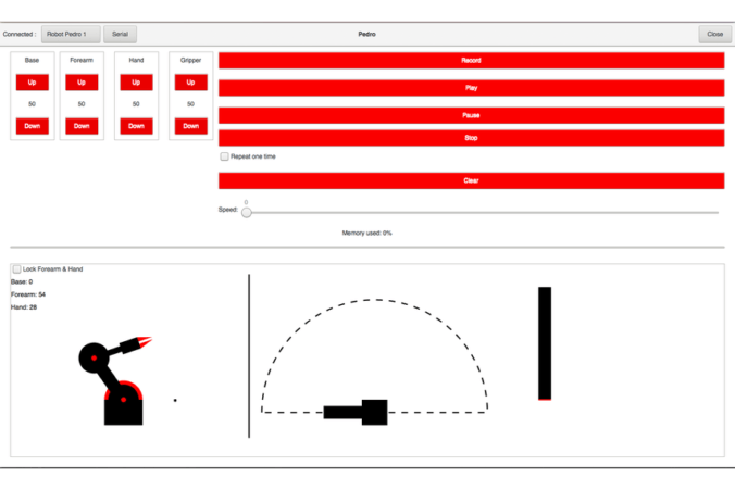 The robot can be controlled via a GUI seen above, and since the control board uses an ATmega328P, it can be programmed via the Arduino IDE. Additionally, the control board includes four potentiometers, allowing an operator to move each axis manually.
